Using an autocollimator to align 4f systems
Posted by Brian Patton, on 29 June 2022
Graeme Johnstone, Brian Patton, Department of Physics and SUPA, University of Strathclyde, Glasgow G4 0NG, United Kingdom
Modern microscope systems comprise many optical elements with precise alignment tolerances. As such, as the complexity of the system increases, the challenge to align them rapidly becomes a major hurdle to implementing home-built designs. One recurring problem is the ability to chain active elements (deformable mirrors, scanning devices, spatial light modulators) in such a way that they are all imaged at conjugate planes. A misalignment of one element can propagate through the system, adding significant aberrations to the overall image.
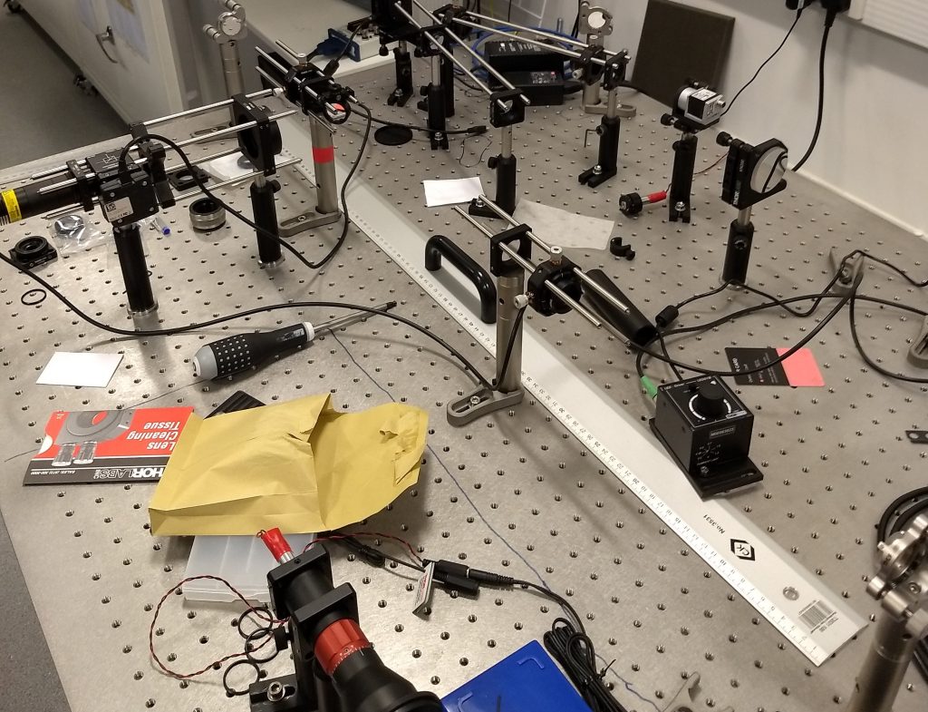
An autocollimator is a very useful tool for a number of applications in an optics laboratory. We use a home built autocollimator that was designed outside our group, by the people behind the openRAMAN project, and the autocollimator is described here. Its operating principal is further described here. This instrument is built from standard optical components and the referenced pages give some further examples of typical applications. While the discussion of autocollimator usage often highlights the ability to measure small angle deviations in an optical path, the ability to measure the focal length of a lens in situ is particularly useful when building and aligning 4f systems in microscopes and other complex imaging experiments. The autocollimator used in the examples below is shown in Fig. 1 and is very similar to the design specified in the aforementioned links. In the Supplemental Note , we present a list of the Thorlabs parts that are used in our autocollimator. We have found it to be such a useful and easy to use apparatus that we keep it permanently constructed, aligned and ready to use.
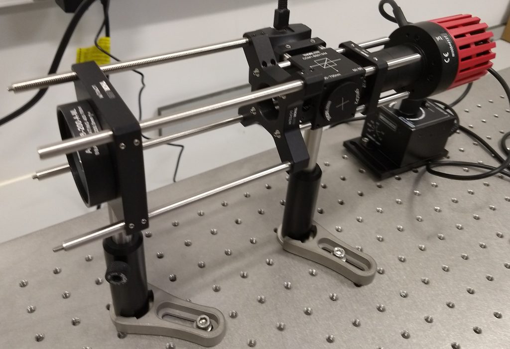
The style of autocollimator used in this article produces collimated light using a bright LED to illuminate a cross shaped reticle. The reticle is aligned to the focal plane of a 200mm focal length achromatic lens. Light from the reticle is therefore collimated when leaving the achromat. A beamsplitter is orientated so that if collimated light is reflected back into the autocollimator it is directed to a camera. The camera is also placed one focal length away from the achromat: if the reticle can be seen in sharp focus on the camera, then the light both leaving and entering the autocollimator is collimated. We can make use of this to very quickly build a 4f system.
Aligning a 4f system
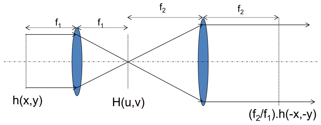
A common task when constructing or re-aligning a microscope is to ensure that devices used for controlling the light, such as beam scanners or adaptive optics elements, are placed at the correct position in the system. For example, one might want to image a deformable mirror onto a Shack-Hartmann sensor to measure the effect of the deformable mirror on the beam. This is most often achieved using two lenses in a 4f configuration: the lenses are separated by the sum of their focal lengths and each device to be imaged is placed one focal length away from one of the lenses. The magnification of the system is unitary when the lenses have equal focal lengths and is the ratio of the focal lengths otherwise. Figure 2 shows a schematic of this layout, along with some key parameters relating to the magnification of the 4f system. The autocollimator can be used to correctly place all 4 components (both lenses and the optical devices external to the 4f system) using the method below. The two optical devices need to be flat reflective surfaces, i.e. mirrors or flattened adaptive optic components for this procedure to work directly. Mirrors may be used in place of components that do not have intrinsic reflective surfaces (for example, a transmissive spatial light modulator (SLM) may not produce enough reflection for this procedure to work directly with the SLM); the position of the mirror when the system is aligned will then correspond to the correct position of the component. It should be noted that using a replacement mirror can lead to a small uncertainty in the position when replacing the mirror with the optical component.
We will now describe the procedure for building a 4f system using an autocollimator with a step by step guide for the simplest case of two optical mirrors and two lenses. To begin, one of the mirrors is placed into a fixed position and rest of the 4f system will be defined from this fixed point. When constructing a microscope this is a common starting point. For example, we often start construction by defining the back focal plane of the imaging objective and then build 4f systems to relay this to the scanning mirrors and then on to any required adaptive optics components.
The initial steps of building the 4f system are shown in Figure 3. With the initial mirror in place, the first lens of the 4f system is placed at approximately its focal length away from the mirror. We find it useful to use optomechanical components that allow the lens to be easily translated along the optical axis of our 4f system. The autocollimator is then placed on the opposite side of the lens from the mirror as shown in Fig. 3. If everything is aligned correctly, the reticle cross should be visible to the camera, though is typically defocussed due the the lens not being correctly positioned from the outset. The lens is moved until the cross is in focus: the first lens is now in the correct location. The in-focus cross can be seen on the monitor screen in Fig. 4.
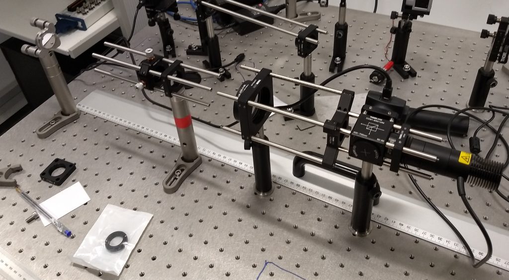
The next step is to put the second lens in rough position such that its distance from the first lens is equal to the sum of the focal lengths of both lenses. Before doing so, the autocollimator will need to be moved from its original position and should be placed so the in-focus reticle cross from the previous step can be seen on the camera and where there is enough space for the other lens to be inserted. This layout is shown in Fig. 4: we have moved the autocollimator, added a cage plate and mount at the correct location for the second lens, but have not yet mounted the lens itself on the cage plate. The second lens can then be put in position and translated axially until the cross is back in focus. At this point we have a collimated 4f system with a mirror at the correct entrance position for the system.
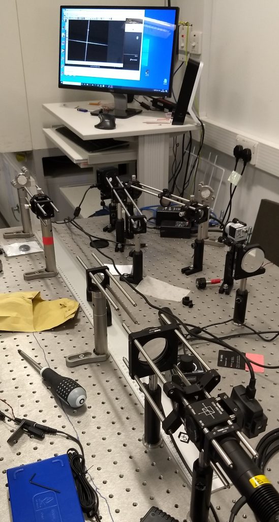
To place the final mirror at the end of the 4f system, the autocollimator needs to be placed between the two lenses, pointing towards the second mirror (the first mirror and lens are not relevant for this final step). The appropriate layout is shown in Fig. 5. In this example, there wasn’t quite enough room to place the autocollimator between the two lenses, so it is positioned in such a way that the light can be coupled into the system by a small drop-in mirror and directed towards the second lens and mirror. The precise location of the drop in mirror is not critical. For this final step, it is the position of the second mirror that should be moved until the reticle cross returns to being in focus. Note the comparison with the first step; the second lens needs to stay in position to keep the 4f system collimated, so by this third step the only degree of freedom remaining for alignment is the position of the second mirror. With the second mirror correctly positioned, we have now aligned the complete 4f system. Depending on the application, we might now need to carefully replace the mirrors by other optical components.
Conclusion
The alignment of relayed optical components can quickly become the most time consuming activity when constructing a complex microscope system. By using an autocollimator, we can rapidly correctly align the typical 4f subunits used in modern microscope designs and then correctly chain them together along the whole optical path. The autocollimator we have used is reliable, easy both to implement and to couple in to the system. We have found it to give extremely reliable results; while it would be possible to calculate the precise accuracy of the system based on the focal length of the achromat and the pixel size of the cameras in the autocollimator we have not felt the need to. For the ~10-300mm focal length lenses used in the typical 4f systems found in our microscopes, the procedure here has consistently resulted in system alignments with better imaging performance that we have achieved by e.g. trying to project collimated lasers through the system and looking for planes of best focus.
It is worth noting that, unlike autocollimator designs that purely translate changes in the optical path to deflections of the beam as measured on the camera, this “imaging” autocollimator has some practical benefits:
- The projected beam is of a large diameter. This effectively means that it maximises the numerical aperture (the sine of the range of angles the light subtends at a focus) when finding the focus of a lens. Since the uncertainty of the measurement of the focal position decreases with increasing NA, this is a significant benefit.
- By using the quality of the focus of an image and not the absolute position (or shift) of the image on the sensor, the autocollimator is robust to small misalignments when coupling into the optical train to be measured.
- Likewise, if only a portion of the outgoing beam is coupled into the optical train (e.g. if the 2″ diameter beam is coupled into a system of 25mm optics), the autocollimator will still be effective. The main impacts with be a decrease in the contrast of the image to be focussed and a small decrease in the accuracy of the measured focal position due to the reduced NA. Note that the reduction in focal accuracy is in line with the maximum NA of the optical train to be aligned, and so reflects a property of the system to be aligned, and not a limitation of the autocollimator itself.
These benefits imply some useful considerations when constructing and using the autocollimator:
- It is not necessary to use the 2″ output lens; a smaller diameter will still be effective. However, there is additional flexbility with using the output lens at this diameter.
- While we showed the autocollimator in-line with the optics being tested for the initial steps, the use of the small turning mirror is step three shows the most effective way we have found to use the autocollimator: we place it on the table somewhere accessible and then use a pair of turning mirrors to couple it into our setup wherever is necessary. This minimises the risk to the autocollimator and is very flexible in terms of in-coupling.
- Finally, it is worth noting that, while we asses the quality of image focus by eye, it would be possible to automate this, and use an autofocus algorithm, coupled to an actuator to move the lenses being aligned. This might be necessary if accurate placement is absolutely critical for a given application.
Supplementary Notes: Parts required to construct an autocollimator
In the autocollimator YouTube video, linked from here, there is a list of parts given that enables everything in the video to be reproduced. However, we found that most of these items are already in a typical optics lab. The table presented below includes the parts that we have used permanently in our autocollimator. Before copying it, we discuss a couple of key points for selection of components.
The first thing to consider is the light source associated with the microscope system that is being constructed or aligned. We mainly want to align optical and near infrared systems and therefore chose a 660nm LED (Thorlabs part M660L4) and a 780nm LED (Thorlabs part M780LP1) for our system. Generally, a LED that is closest in wavelength to the system being aligned is the best choice for the autocollimator.
With regards the camera, the LED is bright enough that we have not found any specific requirement in terms of sensitivity. It is useful to choose one with a c-mount, as that allows it to be easily replaced without re-aligning the autocollimator in the case of hardware failure. While, strictly speaking, there is a relationship between pixel size and absolute accuracy for the autocollimator, we have not worried about this too much – the massive increase in accuracy of alignment we have found already dominates the difference between the ~1-5micon pixel sizes of typical cameras that might be used in this application.
The rest of the parts on this list will be needed for all autocollimators of this design
| Thorlabs Part Number | Name | Quantity |
| DG10-220-MD | Ø1″, SM1-Mounted N-BK7 Ground Glass Diffuser, 220 Grit | 1 |
| R1DS3N | Negative Crosshair Reticle, Ø1″, UVFS | 1 |
| SM1L10 | SM1 Lens Tube, 1.00″ Thread Depth, One Retaining Ring Included | 1 |
| CP36 | 30mm Cage Plate, Ø1.2″ Double Bore for SM1 and C-Mount Lens Tubes | 1 |
| CCM1-BS013/M | 30mm Cage Cube-Mounted Non-Polarizing Beamsplitter, 400-700nm, M4 Tap | 1 |
| LEDD1B | T-Cube LED Driver, 1200mA Max Drive Current | 1 |
| KPS101 | 15V, 2.4A Power Supply Unit with 3.5 mm Jack Connector for One K- or T-Cube | 1 |
| ER2-P4 | Cage Assembly Rod, 2″ Long, Ø6mm, 4 Pack | 1 |
| ER6-P4 | Cage Assembly Rod, 6″ Long, Ø6mm, 4 Pack | 2 |
| ER05-P4 | Cage Assembly Rod, 0.5″ Long, Ø6mm, 4 Pack | 1 |
| ER1-P4 | Cage Assembly Rod, 1″ Long, Ø6mm, 4 Pack | 1 |
| CP33/M | SM1-Threaded 30mm Cage Plate, 0.35″ Thick, 2 Retaining Rings, M4 Tap | 2 |
| LCP06/M | 60mm Cage Plate with Ø2″ Double-Bore Optic Mount, M4 Tap | 1 |
| LCP02/M | 60mm Cage Plate with Ø2″ Double-Bore Optic Mount, M4 Tap | 1 |
| DCC1545/M | USB 2.0 CMOS Camera, 1280 x 1024, Monochrome Sensor | 1 |
| LB1471 | N-BK7 Bi-Convex Lens, Ø1″, f = 50.0mm, Uncoated | 1 |
| AC508-200-A | f=200.0mm, Ø2″ Achromatic Doublet, ARC: 400-700nm | 1 |
| SM1A39 | Adapter with External C-Mount Threads and External SM1 Threads | 1 |
| SM1D12C | SM1 Graduated Ring-Actuated Iris Diaphragm (Ø1 – Ø12mm) | 1 |
 (7 votes, average: 1.00 out of 1)
2 thoughts on “Using an autocollimator to align 4f systems”
Leave a Reply
Get involved
Create an account or log in to post your story on FocalPlane.
More posts like this


Filter by
- NewsApply
- DiscussionsApply
- How toApply
- ToolsApply
- Case studiesApply
- InterviewsApply
- JobsApply
- EducationApply
- Blog seriesApply
- Asian Microscopists ..and Cell BiologistsApply
- AIC at HHMI JaneliaApply
- Deep Learning for Bi..o-image analysisApply
- GloBIAS – updates fr..om the communityApply
- WAMBIAN: West Africa.. in FocusApply
- Volume EMApply
- Latin American Micro..scopistsApply
- Bio-image Analysis w..ith NapariApply
- Imaging with…Apply
- Towards Global Acces..sApply
- Latin America Bioima..gingApply
- From Zero to Qupath ..HeroApply
- Highlights from Euro..-BioImagingApply
- LSFM seriesApply
- DIY MicroscopyApply
- View all
Thanks a lot for writing this article! It triggered a lot of thinking on my part to improve some of our alignment procedures. I’ve built the same autocollimator and have been testing it out for aligning a microscope objective/tube lens/4f system. Here’s a summary of what I have l learned:
1. The autocollimator is really good for axial lens positioning. In my opinion it’s even better than a shear plate. However, it doesn’t help much for the other four degrees of freedom (x, y, tip, tilt) and this matters if you don’t use a cage system or have very tight tolerances that you need to follow on these DOFs. To align these DOFs, you can put a beam splitter immediately after the autocollimator’s 2″ lens with an iris in between, then couple in an alignment laser. (I use the collimated output from a single mode fiber.) I tune the mirror and laser so that the laser is backreflected on itself, then roughly position the autocollimator so that the beam is aligned to it as well. This makes the laser’s path the reference axis, and the goal will be to place all lens surface centers of curvature onto this axis. You can then use laser back reflections and check for forward beam deviations to align lens x, y, tip, and tilt, and then switch to the autocollimator to align the axial position. Iterate until all five DOFs of a lens are aligned.
2. It’s possible to leave the autocollimator and mirror in place when adding all the components (except the camera, see below) without moving it after adding a lens. However, it will be more difficult to find the “x” for every second lens added. This is because the primary image of the reticle is retroreflected if you have an odd number of lenses between the mirror and autocollimator. In retroreflection, a point is imaged onto itself regardless of misalignments of the mirror or lenses. However, for an even number of lenses, the primary image is autocollimated, which means its position is sensitive to misalignment.
3. You can use the autocollimator to place a camera in the focal plane of the lens by moving the autocollimator to the front side of the tube lens/4f system and using the protective glass coating on the camera chip as a parital mirror. You can use the autocollimator’s camera, the camera under alignment, or both to view the “x” and position the camera until both x’s are in focus.
4. I recommend inserting the optics in this order: tube lens, first Fourier lens, second Fourier lens, camera (only x, y, tip, and tilt), objective. I’m still working out the details of the objective and camera alignment, but I rely heavily on the fact that infinity correcteb objectives/tube lens combos are not afocal and thus don’t need precise relative axial positioning.
Thanks again!
Hi,
thank you for documenting your work and making it accessible for the public. I built such an autocollimator myself for measuring angles in our lab. However, I was wondering how to know if the mirror is perpendicular to the optical axis of the autocollimator. The way I understand it, you can measure the change in angle from an initial position just fine but an absolute measurement of the angle of a reflective surface with respect to the optical axis of the autocollimator would require an initial referencing first. Do you have any idea how such a step would look like?
Kind regards,
Paul